


FCCD-64S Series Type Fluxgate Current Sensor
The FCCD-64S series fluxgate current sensor can achieve precise measurement of current, with primary and secondary currents isolated from each other. It boasts advantages such as high accuracy, low temperature drift, and low power consumption, and is powered by dual power supplies. It can be applied to devices such as charging piles, photovoltaic inverters, and UPS systems.
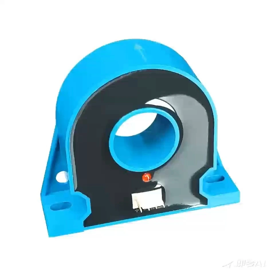
The function indicator light displays the working status of the sensor and indicates whether the function is normal.
More Choices
Feature:
300PPM Accuracy Grade
Dual Power Supply ±12/15VDC
Closed-Loop Zero-flux Detection Technology
Primary And Secondary Isolation Measurement
The Function Indicator Light Displays The Working Status
Advantage:
Stable Accuracy
Low Hysteresis
Strong Anti-interference Ability
Low Temperature Coefficient
Strong anti-interference
Quick Response
Describe
Application :
Electric Vehicle Charging Station
IC-CPD
Frequency Converter
Smart Grid
Energy Storage Power Supply
Medical Equipment
Standardard:
EN50155:2021
EN50121:2017
Size(unit:mm,error:±0.5)
Circuit schematic
Note: This schematic diagram is the basic working principle of the transformer. We can design the transformer sampling circuit for the customer.
Connection method:
Notes: 1. Please input the primary current in the direction indicated in the diagram, and the secondary output current will be positive. 2. The primary current conductor passing through the hole is placed at the center of the hole, achieving the highest accuracy. 2. Static electricity control should be implemented when handling the product. 3. Incorrect wiring methods may cause damage to the sensor. 4. The recommended welding temperature is 265℃±5℃.
Specification
FCCD-64S02
| Basic Electrical Parameters(Ta=25℃.Vcc=±12V) | ||||||
| Project | Symbol | Test Conditions | Minimum | Rated Value | Maximum | Unit |
| Primary Rated Current | IpN | -- | -- | ±100 | -- | A |
| Secondary Rated Current | IsN | -- | -- | ±100 | -- | mA |
| Current Ratio | KN | -- | 1000:1 | -- | ||
| Mesasurement Range | IPM | 1 Minute/Hour | -- | -- | ±120 | A |
| Working Voltage | Vc | Full Range | ±11.4 | ±12 | ±16 | Vdc |
| Current Consumption | Ic | Within The IPM Range | ±20 | ±220 | ±270 | mA |
| Measure Resistance | Rm | -- | -- | -- | 20 | Ω |
| Precision | Xe | @0%~10%IPN | -- | -- | 0.006 | A |
| @10%IPN~IPM | -- | -- | 0.03 | %RD | ||
| Ratio Error | XGe | @0%~10%IPN | -- | -- | 0.006 | A |
| @10%IPN~IPM | -- | -- | 0.03 | %RD | ||
| Phase Error | Xpe | -- | -- | -- | 0.3 | ’ |
| Linearity | EL | -- | -- | -- | 30 | ppm |
| Zero-point Offset Current | IOT | Full Temperature Range | -- | -- | ±0.02 | mA |
| Temperature Drift Coeffoient | TC | -- | -- | -- | 5 | ppm/K |
| Time Drift Coeffoient | TT | -- | -- | -- | 5 | ppm/month |
| Power Supply Anti-Interference | TV | -- | -- | -- | 10 | ppm/V |
| Dynamic Response Time | tr | di/dt=100A/us,
Rise To 90% IPN |
-- | -- | 1 | μs |
| Rate Current Change | di/dt | -- | 100 | -- | -- | A/μs |
|
Bandwidth/-3db |
F | -- | 0 | -- | 100 | kHz |
FCCD-64S04
| Basic Electrical Parameters(Ta=25℃.Vcc=±12V) | ||||||
| Project | Symbol | Test Conditions | Minimum | Rated Value | Maximum | Unit |
| Primary Rated Current | IpN | -- | -- | ±200 | -- | A |
| Secondary Rated Current | IsN | -- | -- | ±200 | -- | mA |
| Current Ratio | KN | -- | 1000:1 | -- | ||
| Mesasurement Range | IPM | 1Minute/Hour | -- | -- | ±250 | A |
| Working Voltage | Vc | Full Range | ±11.4 | ±12 | ±16 | Vdc |
| Current Consumption | Ic | Within The IPM Range | ±20 | ±220 | ±270 | mA |
| Measure Resistance | Rm | -- | -- | -- | 20 | Ω |
| Precision | Xe | @0%~10%IPN | -- | -- | 0.006 | A |
| @10%IPN~IPM | -- | -- | 0.03 | %RD | ||
| Ratio Error | XGe | @0%~10%IPN | -- | -- | 0.006 | A |
| @10%IPN~IPM | -- | -- | 0.03 | %RD | ||
| Phase Error | Xpe | -- | -- | -- | 0.3 | ’ |
| Linearity | εL | -- | -- | -- | 30 | ppm |
| Zero-point Offset Current | IOT | Full Temperature Range | -- | -- | 0.02 | mA |
| Temperature Drift Coeffoient | TC | -- | -- | -- | 5 | ppm/K |
| Time Drift Coeffoient | TT | -- | -- | -- | 5 | ppm/month |
| Power Supply Anti-Interference | TV | -- | -- | -- | 10 | ppm/V |
| Dynamic Response Time | tr | di/dt=100A/us,
Rise To 90% IPN |
-- | -- | 1 | μs |
| Rate Current Change | di/dt | -- | 100 | -- | -- | A/μs |
| Bandwidth/-3db | F | -- | 0 | -- | 100 | kHz |
FCCD-64S05
| Basic Electrical Parameters (Ta=25℃.Vcc=±12V) | ||||||
| Project | Symbol | Test Conditions | Minimum | Rated Value | Maximum | Unit |
| Primary Rated Current | IpN | -- | -- | ±300 | -- | A |
| Secondary Rated Current | IsN | -- | -- | ±300 | -- | mA |
| Current Ratio | KN | -- | 1000:1 | -- | ||
| Mesasurement Range | IPM | 1Minute/Hour | -- | -- | ±360 | A |
| Working Voltage | Vc | Full Range | ±11.4 | ±12 | ±16 | Vdc |
| Current Consumption | Ic | Within The IPM Range | ±20 | ±220 | ±270 | mA |
| Measure Resistance | Rm | -- | -- | -- | 20 | Ω |
| Precision |
Xe | @0%~10%IPN | -- | -- | 0.006 | A |
| @10%IPN~IPM | -- | -- | 0.03 | %RD | ||
| Ratio Error |
XGe | @0%~10%IPN | -- | -- | 0.006 | A |
| @10%IPN~IPM | -- | -- | 0.03 | %RD | ||
| Phase Error | Xpe | -- | -- | -- | 0.3 | ’ |
| Linearity | εL | -- | -- | -- | 30 | ppm |
| Zero-point Offset Current | IOT | Full Temperature Range | -- | -- | 0.02 | mA |
| Temperature Drift Coeffoient | TC | -- | -- | -- | 5 | ppm/K |
| Time Drift Coeffoient | TT | -- | -- | -- | 5 | ppm/mont |
| Power Supply Anti-Interference | TV | -- | -- | -- | 10 | ppm/V |
| Dynamic Response Time | tr | di/dt=100A/us,
Rise To 90% IPN |
-- | -- | 1 | μs |
| Rate Current Change | di/dt | -- | 100 | -- | -- | A/μs |
| Bandwidth/-3db | F | -- | 0 | -- | 100 | kHz |
FCCD-64S06
| Basic Electrical Parameters (Ta=25℃.Vcc=±12V) | ||||||
| Project | Symbol | Test Conditions | Minimum | Rated Value | Maximum | Unit |
| Primary Rated Current | IpN | -- | -- | ±400 | -- | A |
| Secondary Rated Current | IsN | -- | -- | ±400 | -- | mA |
| Current Ratio | KN | -- | 1000:1 | -- | ||
| Mesasurement Range | IPM | 1Minute/Hour | -- | -- | ±500 | A |
| Working Voltage | Vc | Full Range | ±11.4 | ±12 | ±16 | Vdc |
| Current Consumption | Ic | Within The IPM Range | ±20 | ±220 | ±270 | mA |
| Measure Resistance | Rm | -- | -- | -- | 20 | Ω |
| Precision | Xe | @0%~10%IPN | -- | -- | 0.006 | A |
| @10%IPN~IPM | -- | -- | 0.03 | %RD | ||
| Ratio Error | XGe | @0%~10%IPN | -- | -- | 0.006 | A |
| @10%IPN~IPM | -- | -- | 0.03 | %RD | ||
| Phase Error | Xpe | -- | -- | -- | 0.3 | ’ |
| Linearity | εL | -- | -- | -- | 30 | ppm |
| Zero-point Offset Current | IOT | Full Temperature Range | -- | -- | 0.02 | mA |
| Temperature Drift Coeffoient | TC | -- | -- | -- | 5 | ppm/K |
| Time Drift Coeffoient | TT | -- | -- | -- | 5 | ppm/mont |
| Power Supply Anti-Interference | TV | -- | -- | -- | 10 | ppm/V |
| Dynamic Response Time | tr |
di/dt=100A/us, Rise To 90% IPN |
-- | -- | 1 | μs |
| Rate Current Change | di/dt | -- | 100 | -- | -- | A/μs |
| Bandwidth/-3db | F | -- | 0 | -- | 100 | kHz |
Note: If there is no product suitable for your use in the above table, we can tailor the product according to your technical and structural requirements.
For more information about our products, welcome to contact us at any time!