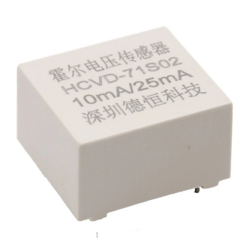
HCVD-71S Series
DESCRIPTION:
Hall Effect voltage Sensor
Rated input current: 5-10mA DC or AC
Rated output current: ±25mA
Power supply: ±12~±15(5%)
PIN type, PCB install
It can be used to measure currents signal including DC,AC,high frequency and various irregular waveforms Epoxy potting, Safe and reliable
More Choices
ADVANTAGES:
High precision, Good linearity;
Low temperature drift, Good overload capacity.
Wide band frequency, Quick response.
Strong anti-interference ability
APPLICATIONS:
UPS Switching power supply
Inverter Frequency control system
Robot Grid monitoring
Size
Circuit schematic
Electrical schematic:
Instructions for use:
1.When measuring the voltage, Ri is connected in series on the primary side of the sensor. Try to choose the appropriate size of Ri so that the input current is the rated current.
2.Voltage measure range:10-500V,To ensure the stability of the measured resistance, the power of Ri is more than 4 times the rated power.
3.Connect the current according to the calibration direction of the circuit diagram, pay attention to the direction of current.
Specification
|
Parameter |
HCVD-71S01 |
HCVD-71S02 |
Unit |
|
Rated input(Ipn) |
5 |
10 |
mA |
|
Measure range(Ip) |
7 |
14 |
mA |
|
Turns ratio(Np/Ns) |
5000:1000 |
2500:1000 |
T |
|
Measure resister |
±12V ±15V 10mAmax 350(max) 14mAmax 190(max) |
Ω |
|
|
Rated output(Isn) |
±25 |
mA |
|
|
Supply voltage |
±12 ±15 |
V |
|
|
Power consumption |
≤10+Is |
mA |
|
|
Zero offset current |
≤±0.15 |
mA |
|
|
Offset current drift |
-40~+85℃ ≤±0.01 |
mA/℃ |
|
|
Linearity |
≤0.2 |
% |
|
|
Precision |
≤0.5 |
% |
|
|
Response time |
<40 |
µS |
|
|
Galvanic isolation |
4.0 |
kV |
|
Note: If there is no product suitable for your use in the above table, we can tailor the product according to your technical and structural requirements.
For more information about our products, welcome to contact us at any time!


