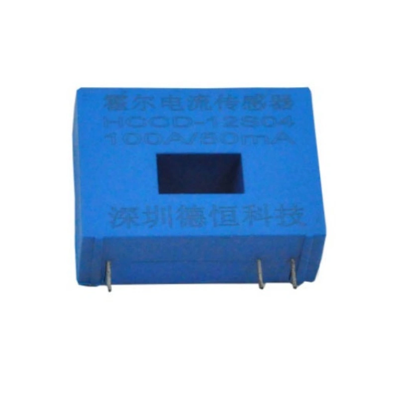
HCCD-12S Series Hall Current Sensor
This is new type of hall current sensor, it can be used to measure currents signal including DC, AC, high frequency, pulses and various irregular waveforms
More Choices
Describe
Applications:
UPS Switching power supply
IInverter Frequency control system
Robot Grid monitoring
Size
Circuit schematic
Note: This schematic diagram is the basic working principle of the transformer. We can design the transformer sampling circuit for the customer.
Electrical schematic:
Instructions for use:
1、Connect the current according to the calibration direction of the circuit diagram, pay attention to the direction of current.
2、The temperature of the primary conductor should not exceed 100 ° C。
Specification
|
Model PARAMETERS |
HCCD-12S01 | HCCD-12S02 | HCCD-12S03 |
HCCD-12S04 |
Unit |
| Input current | 25 | 50 | 75 | 100 | A |
| Measuring range | 50 | 70 | 105 | 150 | A |
| Current ratio | 1:1000 | 1:1000 | 1:1500 | 1:2000 | |
| Output Current | 25 | 50 | 50 | 50 | mA |
| Loaded resistance | ≤30 | ≤30 | ≤60 | ≤100 | Ω |
| Supply voltage | ±12~±15 | V | |||
| Current consumption | 12+Is | mA | |||
| Zero offset voltage | <±0.2 | mA | |||
| Offset voltage temperature drift | <±0.1 | mA/℃ | |||
| Linearity |
0.2 ( T=25℃) |
% |
|||
| Accuracy |
0.5 |
% |
|||
| Response |
<1 |
µS |
|||
| Insulation hipot |
4.5 |
kV/Min |
|||
| Insulation resistance |
≥500 |
MΩ |
|||
| -3db band width |
DC…100 |
kHz |
|||
| Working temperature range |
-20~+80 |
℃ |
|||
| Storage temperature range |
-40~+90 |
℃ |
|||
Note: If there is no product suitable for your use in the above table, we can tailor the product according to your technical and structural requirements.
For more information about our products, welcome to contact us at any time!


