


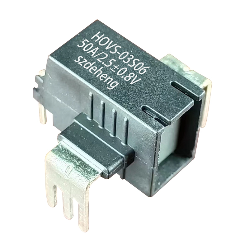
HOVS-03S Series Hall Current Sensor
Hall Effect Current Sensor
Rated input current: 10-50A DC or AC
Rated output voltage: 2.5±0.8V
Power supply: +2.5±0.5V
PIN type, PCB install
Feature:
1.Primary and secondary isolation, pressure and safety.
2.It can be used for detecting of DC,AC, high frequency, pulse as well as various of irregular wave of current signals.
More Choices
FEATURES:
● Multi-range current sensor
● Power supply: +5V
● Voltage output, benchmark:2.5V
● Low power consumption
● Compact design for easy PCB mounting
● High bandwidth, low loss
● Complete isolation between primary and secondary
APPLICATIONS:
● AC frequency conversion speed regulating equipment
● DC motor
● UPS
● Switching power supply
● Welding machine power supply
● Communication power supply
ADVANTAGES:
● High precision
● Low insert loss
● Strong anti-interference ability
● Low temperature coefficient
● Large measuring range 3*IPN
● Small size, saving space
● Insulation voltage 4kVAC
GUIDELINE:
● UL 508:2010
● EN 50178:1997
● IEC 61010-1:2010
● IEC 61326-1:2012
Size
Circuit schematic
PCB package size chart:
Precautions
1.The electrical parameter test conditions are TA=25℃, UC=5V, RL=10kΩ (load resistance).
2.When the IP current flows in the direction shown by the arrow in the figure above, Vout is a positive value relative to Vref.
3.Wrong wiring method may cause damage to the sensor.
4.The recommended welding temperature is 265℃±5℃.
5.After the product is welded, it can be potted with flexible silicone only or covered with conformal paint. Epoxy resin potting is not allowed. Conformal anti-paint and silicone cannot be used at the same time, as it may cause PCBA corrosion. The product shell is acid and alkali resistant and will not react chemically with conformal paint and glue.
Specification
|
Maximum rated parameters |
||
|
Item |
Value |
Unit |
|
Supply voltage (non-destructive) |
6.5 |
V |
|
Electrostatic discharge voltage (HBM-Human Body Model) |
2 |
kV |
Note: Pressures exceeding these levels may cause permanent damage, and prolonged exposure to absolute maximum ratings may reduce stability.
|
Basic rated parameters |
||
|
Item |
Value |
Unit |
|
Main circuit voltage |
600 |
V |
|
Primary current |
According to the rating |
A |
|
Secondary supply voltage |
5 |
V DC |
|
Output volyage |
0-5 |
V |
|
Ambient temperature |
-40~105 |
℃ |
|
Working temperature range |
-40~105 |
℃ |
|
Insulating properties |
|||
|
Item |
Value |
Unit |
Conditions |
|
Insulation voltage |
>4 |
kV |
50Hz/1min |
|
Impact resistance |
≥6 |
kV |
1.2/50μs |
|
Electrical clearance |
8 |
mm |
shortest distance in space |
|
Creepage distance |
8 |
mm |
The shortest distance along the body |
|
Housing material |
UL 94V0 |
|
|
|
Relative tracking index |
600 |
|
|
|
Applications |
600V CAT lll PD2 |
V |
According UL508 |
Customizable:
This specification is a standard product. If other technical parameters are required, our company can customize it for customers.
|
Model Parameters |
HOVS-03S01 |
HOVS-03S02 |
HOVS-03S03 |
Unit |
|
Input current |
10 |
16 |
20 |
A |
|
Measuring range |
±25 |
±40 |
±50 |
A |
|
Output voltage |
2.5±0.8 |
V |
||
|
Reference voltage |
2.5±0.02 |
V |
||
|
Loaded resistance |
≥10 |
kΩ |
||
|
Power supply |
5±0.5 |
V |
||
|
Current consumption |
<25 |
mA |
||
|
Zero offset voltage |
<5 |
mV |
||
|
Temperature Coefficient - |
<170 |
ppm/K |
||
|
Temperature coefficient - output |
<0.075 |
mV/K |
||
|
linear error |
0.5 |
% |
||
|
Accuracy |
1.0 |
% |
||
|
Response |
<2 |
µS |
||
|
-3db band width |
DC…400 |
kHz |
||
|
Model Parameters |
HOVS-03S04 |
HOVS-03S05 |
HOVS-03S06 |
Unit |
|
Input current |
32 |
40 |
50 |
A |
|
Measuring range |
±80 |
±100 |
±125 |
A |
|
Output voltage |
2.5±0.8 |
V |
||
|
Reference voltage |
2.5±0.02 |
V |
||
|
Loaded resistance |
≥10 |
kΩ |
||
|
Power supply |
5±0.5 |
V |
||
|
Current consumption |
<25 |
mA |
||
|
Zero offset voltage |
<5 |
mV |
||
|
Temperature Coefficient - |
<170 |
ppm/K |
||
|
Temperature coefficient - output |
<0.075 |
mV/K |
||
|
linear error |
0.5 |
% |
||
|
Accuracy |
1.0 |
% |
||
|
Response |
<2 |
µS |
||
|
-3db band width |
DC…400 |
kHz |
||
For more information about our products, welcome to contact us at any time!